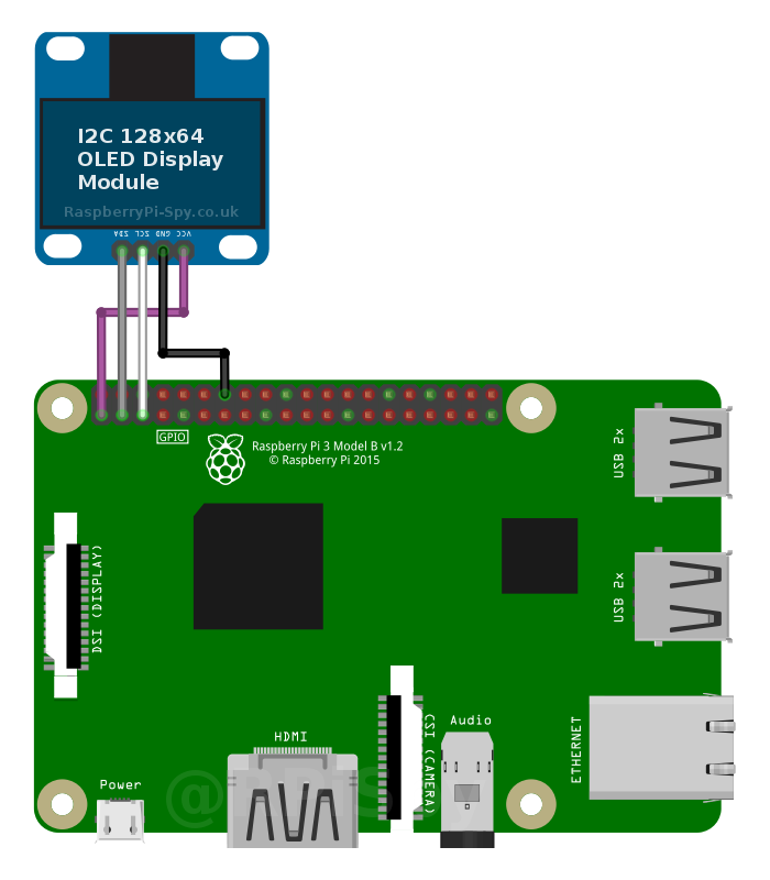
Connecte the wires directly to the Raspberry Pi’s GPIO header using the following scheme, double check the Labels on the OLED itself.
- VCC -> GPIO 1 *
- GND -> GPIO 14 **
- SCL -> GPIO 5
- SDA -> GPIO 3
* You can connect the Vcc pin to either Pin 1 or 17 as they both provide 3.3V
** You can connect the GNDpin to either Pin 6, 9, 14 , 20, 25, 30, 34 or 39 as they all provide Ground.